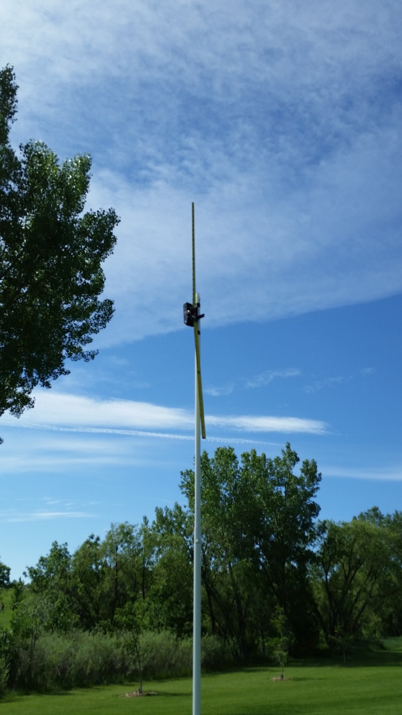

1) A small, battery powered oscillator with a 46 inch long dipole that could be mounted on a pole 10 feet in the air. The transmitting antenna could be oriented either vertically or horizontally. See below:
Vertical Orientation Horizontal Orientation


2) Two receiving antennas were used; A 21
inch diameter, tuned loop and a 61 inch long dipole with dual, high impedance,
battery powered buffer amplifiers. These antennas could, also, be
oriented either vertically or horizontally. See Below:
Tuned loop Receiving Dipole with Dual High Impedance Buffer Amplifiers
3) A Perseus receiver along with a laptop was used for recording the measurements. See Below:
Perseus Display from LapTop
Perseus HF Receiver
The transmitting antenna was placed on a fiberglass pole about 10 feet off the ground and manually oriented for all tests. The receiving apparatus was located about 260 feet away from the transmitter which transmitted on 7.159 MHz. The receiving antennas were hand held about 6 feet from the ground and, also, manually oriented. Keep in mind that the dipole has dual high impedance buffer amplifiers , so it cannot be compared directly in signal strength with the tuned loop. Also, the nulls of both antennas are probably not as great as possible because the nulls are very sensitive to orientation. However, the general polarization comparisons are valid. The results are tabulated below:
Results
Observations:
1) The received signal is strongest with vertical polarization probably because the antennas proximity to the ground. This is observed because the stronger signal is from both dipoles oriented vertically as opposed to both dipoles being oriented horizontally. This has been borne out in my RFI tracking from RFI originating from residences.
2) The signal off the end of the horizontal transmitting antenna is mostly vertically polarized.
3) Looking through the loop (Picture A in the chart above) toward the transmitter produces a null for vertically polarized signals. The peak for the loop occurs when the loop is rotated 90 degrees (Picture B in the chart above) looking along the edge of the loop toward the transmitter.
4) Picture D shows picture A rotated 90 degrees so that the plane of the loop is parallel to the ground.
5) The orientation of the receiver dipole (Pictures D, E, and F) with respect to the transmitter dipole is more obvious from the pictures.
6) If the transmitter antenna is oriented horizontally,
the received signal becomes horizontally polarized when you are very close
to the transmitting antenna.